

Hydrogen Air Compressor

Hydrogen Air Compressor
High-Performance Hydrogen Pressurization System
Product Description
The hydrogen compressor skid is an independent The complete system can be used when connected to the gas source, cooling and power supply. The main equipment of the hydrogen compressor skid system is To include:
1. Steel structure skid, including chassis, equipment support inside the skid, instrument bracket, etc., as well as electrical and instrument protection Explosion junction box, fixed installation components of the skid body, and grounding components;
2. The upstream and downstream straight pipe sections of the hydrogen compressor, filters, hydraulic drive system of the liquid-driven hydrogen compressor, necessary instruments for the compressor inlet and outlet pipelines, and the pressure transmitter and temperature transmitter supporting the compressor;
The skid valves include:
(1) Stop valves, ball valves, safety valves, discharge valves, etc. upstream/downstream of the booster pipeline;
(2) The cooling system piping in the skid includes pipes, stop valves, flow meters, etc.;
(3) All valves included in other auxiliary systems in the skid that are set up to achieve the intended functions;
3. Pipe section and flange connected to the owner's pipeline and matching flange at the connection with the user; connecting pipe inside the skid Line and pipe accessories;
4. Pressure and temperature instruments installed in the skid according to the requirements and relevant specifications;
5. Flame alarms and hydrogen concentrations installed in the skid to achieve the intended functions and in accordance with relevant specifications Detectors, exhaust fans and other equipment;
6. A complete set of electrical control systems for the entire skid electrical control.
Composiiton
The outer shell of the skid is made of steel that meets the strength requirements. The surface of the skid is spray-painted to prevent rust and corrosion, and to provide sun and rain protection. The appearance of the skid can be adjusted according to the customer's appearance requirements.
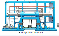
The core part of the hydrogen compressor skid is the hydrogen compressor, which mainly includes power Hydraulic drive system and hydrogen boosting / preurization system, as shown in the figure

The hydraulic system mainly consists of a motor, oil pump, oil tank, reversing valve group, oil cooler, rack, instruments and meters. As shown:
The hydrogen booster system mainly includes a frame, hydraulic cylinder, cylinder, intake pipe, exhaust pipe, purge pipe, The schematic diagram of the hydrogen boosting system is shown in the figure. As shown:
Our Advantages
The product is driven by an explosion-proof motor in the hydraulic drive system, which drives the hydraulic oil pump to actuate the piston in the hydrogen pressurization system, compressing the hydrogen gas.
The hydrogen pressurization system adopts single-stage compression. The pressurization system integrates a cooling system and has a compact structure.
A. Product Highlights-Oil isolation technology
Compared with the oil-isolating sealing structure of competitors, the LexFlow brand's unique cylinder seal + isolation chamber oil-isolating structure implements double isolation and protection of oil. The oil film part of the piston rod is isolated from the cylinder, which prevents oil from entering the cylinder and contaminating the medium at the molecular level. Build a "pollution-free" hydrogen refueling station.
B. High-efficiency spiral liquid cooling technology - calmly cope with various working conditions
The compressor cylinder adopts a 360-degree spiral cooling structure with no dead ends. The heat transfer efficiency is improved through structural optimization and the cooling capacity of the cooling medium is fully utilized. The exhaust temperature is 10°C lower than the exhaust temperature of conventional structures.
Product Features
Key technical features
Compared with traditional methods, liquid-driven hydrogen compressors have the following advantages:
(1) The equipment runs at a low speed and has little vibration;
(2) Multiple protection devices make operation safer;
(3) The structure is classical and of reasonable design;
(4) The exhaust volume can be adjusted to protect the environment;
(5) One machine can be used for multiple purposes, such as filling the car, emptying the tank, etc., to meet the various needs of users;
(6) Simple maintenance and low overall use cost;
(7) Frequent start and stop are suitable for real working conditions;
(8) Oil-free lubrication is safe and reliable;
(9) The piston seal has a long service life and no pollution
Product Parameters
| Model | LFC-D-470/50-200/450 | LFC-D-470/50-200/450 | LFC-D-940/50-200/450 | LFC-D-1410/50-200/450 | LFC-D-1880/50-200/450 |
| Stage | 2 | 1 | 1 | 1 | 1 |
| Medium | H2 | H2 | H2 | H2 | H2 |
| Rated output | 470Nm3 ( 500kg/12 h ) | 470Nm3 ( 500kg/12 h ) | 940Nm3 ( 1000kg/12 h ) | 1410Nm3 ( 1500kg/12 h ) | 1880Nm3 ( 2000kg/12 h ) |
| Inlet pressure | 5Mpa ~ 20 Mpa | 5Mpa ~ 20 Mpa | 5Mpa ~ 20 Mpa | 5Mpa ~ 20 Mpa | 5Mpa ~ 20 Mpa |
| Inlet temp. | -20ºC ~ +45ºC | -20ºC ~ +45ºC | -20ºC ~ +45ºC | -20ºC ~ +45ºC | -20ºC ~ +45ºC |
| Outlet temp. | ≤45ºC | ≤45ºC | ≤45ºC | ≤45ºC | ≤45ºC |
| Max working pressure | 45MPa | 45MPa | 45MPa | 45MPa | 45MPa |
| Power | 55KW | 90KW | 110KW | 145KW | 180KW |
| Noise | ≤85Db ( distance 1 m) | ||||
| Explosion -proof | Ex d e mb IIC T4 Gb | ||||


PREV:It's already number one.
NEXT:That's the last one